

Assembling help
Electrical board:
- cut a 5x5 cm peace from the prototype board
- place the 3,5mm jack connector to the top left corner of the board and solder it in
- place the other one 3,5 mm jack connector to the bottom left corner of the board and solder it in
- you should connect each other the two channels with an isolated slim wire
- place the pin headers according to the schematic diagram (a single circle in the diagram equals a pair of pin headers) and solder these in
- to connect the signal and the ground pins of the jack into the circuit use an isolated slim wire
- you may need to cut the pad stripe at some places with a sharp knife
- you need to solder the receptacle pairs to the electrical components (resistor, inductor and capacitor) to these will be connectable in the circuit
- it is easy if you put the receptacles on the pins, melt much solder wire on the components pad’s and electrodes’ and solder these to the receptacles

Mechanical board:
- cut a 5x5 cm peace from the prototype board
- place to the top left corner of the board the USB-B type connector
- bend its two fixings in horizontal position and solder it in (you have to cut the pad stripe between the pins of the USB connector)
- to fix the USB connector to the board you should make two hooks from a cut off electrode of a resistor and solder these to the USB fixings and also the board
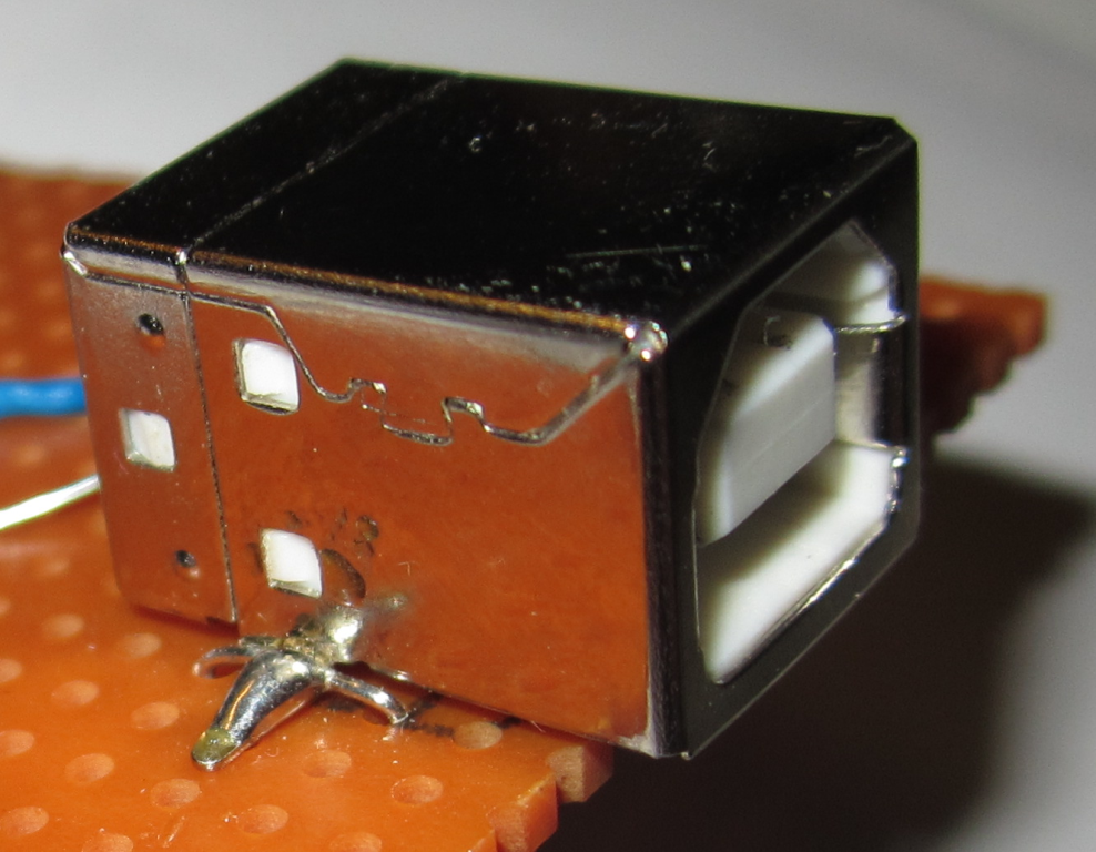
- solder the CNY70 sensor to the right bottom corner of the board (the caption of the sensor need to be the right edge of the board)
- you have to cut the pad stipe between the pins of the sensor
- solder the 3,5 mm jack connector to the bottom left corner of the board
- you should connect each other the two channels with an isolated slim wire
- connect the signal pins of the jack to the bottom left pin of the sensor (in lower view) with an isolated slim wire
- connect the ground pin of the jack to the top left pin of the sensor (in lower view) with an isolated slim wire
- connect the pin one of the USB connector to the top right pin of the sensor with the 220 ohm resistor to supply the infrared LED of the sensor
- connect the pin four of the USB connector to the bottom right pin of the sensor with an isolated slim wire
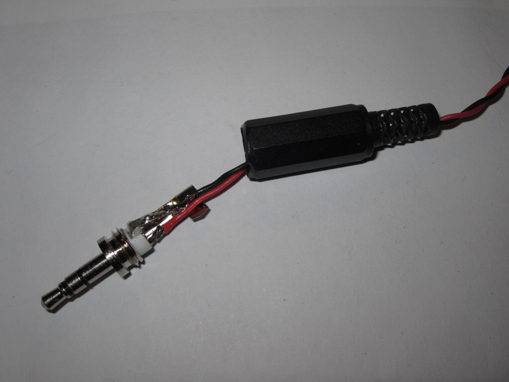
- for the electrical and mechanical board you may need to make two jack-jack cable
- solder the ground wire of the 2 conductor cable to the ground of the jack plug and the signal wire to the signal pad of the jack plug (the coat of the jack plug let it be on the cable)
- do it at the other end of the cable and make another same jack-jack cable
The publication/presentation is supported by the European Union and co-funded by the European Social Fund. Project title: ‘Telemedicine-focused research activities on the field of Mathematics, Informatics and Medical sciences’ Project number: TÁMOP-4.2.2.A- 11/1/KONV-2012-0073.